To Block or Not to Block? RF Switch Matrix Selection Questions
What do you know about selecting an RF Switch Matrix?
Our Principal Engineer, Jeff Gibala, has written a very informative paper to help you choose your next RF switch matrix. He not only covers the types and configurations, but dives into the nuances and benefits of various electrical parameters that impact your selection.
Information on the several types to choose from when selecting the right RF switch matrix for your application:
- Blocking
- Non-Blocking
- Super Non-Blocking
Turn the complex into the simple with details about the various electrical parameters that impact your selection:
- Operation Frequency
- Insertion Loss
- Isolation
- Desired Switching Times, and
- RF Power Levels Being Used
Download your FREE copy now.
Choosing RF Switches for High-Power Applications
Download Now
It looks like Javascript isn't enabled in your browser. Please enable it in order to fill out this form.
 RF Switch Matrices
Introduction
RF switch matrices eliminate the need to manually move connections by routing signals, via user control, from their input ports to their output ports, providing convenience and speed to many industrial applications. They can be used in production environments for switching test equipment, like signal generators, spectrum analyzers, network analyzers, power meters, etc., to a device under test. A switch matrix can also be used to create redundancy paths to back up equipment, like feeds from antennas to receivers. They can also be used in labs to split and distribute a signal to multiple places or to create multiple signal paths with differing characteristics, such as delay, frequency response, or attenuation.
Switch Matrix Types
There are three different types of matrices that provide different functionality. These types are blocking, non-blocking, and super non-blocking. All types are denoted as NxM, where the letter “N” designates the quantity of input ports, and the letter “M” denotes the number of output ports. For example, a matrix designated as a 4x4 has four input ports and four output ports. A switch matrix could be as simple as a 1x2, as complex as a 256 x 256, or anywhere in between.
Blocking Switch Matrix
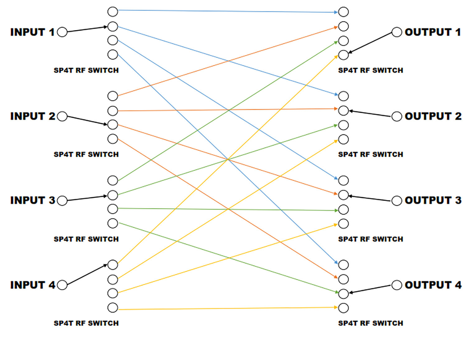 A blocking switch matrix allows an input port to be connected to any of its output ports. At any given instant, an input can only be connected to one output, and each output can only be connected to one input. In a blocking matrix, the number of active connections is limited to the number of input or output ports, whichever is less. For example, in a 1x4 blocking switch matrix, there can only be one active connection at a time.
The diagram to the right shows the possible pathways that exist in a 4x4 blocking switch matrix. This type of switch matrix can be realized by a quantity of eight Single Pole Four Throw switches, and 16 interconnecting cables. By examining the diagram, you can see that there can only be four simultaneous connections. At any given instant, a single input can be connected to one of the outputs, and that one output can only be connected to one input.
Non-Blocking Switch Matrix
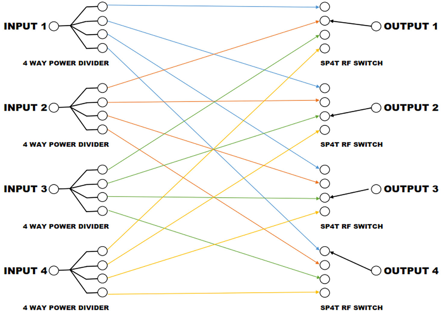 Another type of RF switch matrix is the non-blocking type. In a non-blocking switch matrix, an input can be simultaneously connected to multiple outputs, but at any instant, each output can only be connected to one of the inputs. To provide this functionality, each input signal is split using a power divider.
The following diagram shows the possible interconnections in a 4x4 non-blocking switch matrix. This switch matrix requires a quantity of four 4-way power dividers, four Single Pole Four Throw switches, and 16 interconnecting cables. Since the power dividers split the input signal four ways, providing a copy of each input to each output at all times, a single input can be connected to any number of outputs at the same time. Because each input is split, the signal at each output is a lower amplitude than the input signal.
Super Non-Blocking Switch Matrix
 The last type of switch matrix architecture is the super non-blocking type. This type of switch matrix allows the inputs to be simultaneously connected to multiple outputs, and the outputs to be simultaneously connected to multiple inputs. To achieve this level of connectivity, each input signal must be split to divide the input signal to all the outputs. Each output must use a combiner to sum the signals from each input onto a common output.
The diagram to the right shows a 4x4 super non-blocking switch matrix. It consists of eight power dividers (four are used to split the input signal, and four are used as combiners at the output), 16 Single Pole Single Throw switches, and 16 interconnecting cables.
You can see from this diagram that any number of inputs can be connected to any number of outputs by simply turning the appropriate switch on or off. Because of the need to have splitters and combiners at the input and output, the signal level at the output is lower in amplitude than the input signal.
Electrical Parameters
Besides the basic functional types of blocking, non-blocking, and super non-blocking, there are electrical parameters that are common to all switch matrices. These parameters include operating frequency, insertion loss, isolation, switching time, and operational power level. The requirements for just one of these parameters can drive the switch matrix design and limit what is obtainable for the remaining parameters. This limitation means trade-offs must often be made in the overall specifications to meet critical requirements.
Operating Frequency
The frequency range of the RF signal that can pass from the input port to the output of the matrix is its operating frequency range. Matrices can be designed to operate over a wide frequency range, such as DC to 40GHz, or a narrower range, like 2.4GHz to 2.5GHz. The wider the bandwidth of a matrix, the more expensive it will be. Also, operation down to DC, or very low frequencies, limits the types of switches that can be used to build the matrix and will impact other specifications, such as switching speed and insertion loss.
Insertion Loss
The insertion loss of a switch matrix is a measure of the RF signal power lost when traveling from the input to the output. The loss is measured in dB, and any components (splitters, switches, cabling etc.) in the signal path contribute to the insertion loss value. The non-blocking and super non-blocking matrices inherently have higher insertion loss than a blocking matrix because they require power dividers and power combiners in addition to switches. The super non-blocking matrix has the highest insertion loss.
The insertion loss could be further impacted by the required bandwidth. Power dividers that operate over a wide frequency range, such as 1GHz to 40GHz have insertion loss that is higher than narrower band devices. The same is true of power dividers that operate down to DC. Higher insertion loss can be expected with wider operating bandwidths and lower operating frequencies unless other measures are taken.
Amplifiers can be added to the matrix signal paths to boost the signal’s power level to offset any components’ losses and to keep the insertion loss low. But amplifiers cannot be added if the matrix is required to be bi-directional. A bi-directional matrix will allow signals to flow from input to output as well as to flow from output to input. Adding amplifiers will make the matrix uni-directional, where signals can flow in only one direction from input to output.
Isolation
Isolation is a measure of the signal power loss through a matrix when that path is turned off, and the loss between ports never directly connected. Isolation can be measured from input to output, input to input, or output to output. In all cases, the higher the isolation, the better. In some applications, very high isolation is desired to keep signals from different ports or paths from leaking into each other and causing interference.
Switching Time
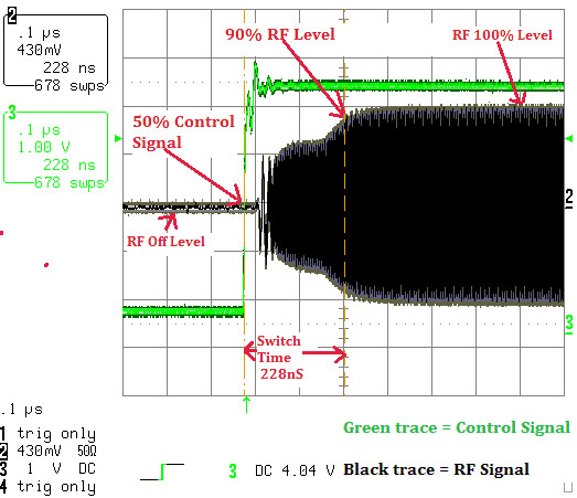 The time it requires the switch matrix to disconnect from one path and establish a new path connection is the switching time. The switching time is measured with respect to a control signal that tells the switch matrix to change states. The elapsed time from this control signal until the RF signal is at 10% or 90% of its final voltage is the switching time. During the switching time interval, the control signal must be processed, and all necessary switches must be set to the proper state. This parameter is primarily set by delays in the matrix control circuitry and the characteristics of the signal switches.
The types of switches used within the matrix have a large effect on the switching time. Mechanical switches, such as coaxial relays or waveguide switches, are the slowest and have switch times in the tens of milliseconds range. PIN diode and FET-based switches are the fastest and can have switch times in the tens of nanoseconds range. If achieving the fastest possible switching time is a crucial requirement, it may serve as the driver regarding the other characteristics of the switch matrix.
As mentioned earlier, matrix control methods also influence switching time. For example, if the control signal is delivered via a network connection, there is time required for the signal to be routed through the communications network as well as time required for the controller within the matrix to receive and decode the control signal. Switch matrices with critically fast switching times require low latency direct connected control signals. In applications where pre-defined sequenced switching needs to happen at the highest speeds, a program can be pre-loaded into the switch matrix and run by issuing a single command.
RF Power Levels
The power levels of the RF signals that the switch matrix must pass have an impact on overall performance specifications. The different types of switches used for matrix construction have varying operating power levels. Mechanical coaxial relays can handle from tens to thousands of watts depending on the signal frequency. In contrast, PIN diode switches and FET-based switches can only handle power in the tens to hundreds of watts.
The other factor limiting RF power levels into the switch matrix is the presence of signal amplifiers. Switch matrices that contain amplifiers to offset losses must be designed with the input signal power levels in mind. Incorrect sizing or placement of the amplifier can cause adverse effects, such as signal distortion and possible component damage. Care must be taken to properly design the matrix for the best possible performance at the required RF signal levels.
Controls
Switch matrices can be controlled manually or by computer. Typically, both types are provided with a front panel knob or a touch screen common for manual control. For computer-controlled switches, discrete control bits, Ethernet, RS232, or USB are very common. Protocols for computer-controlled switches can be customized to meet specific user requirements.
Reliability
Switch matrix reliability is mainly driven by the type of switches used. Mechanical coaxial relays have a limited life, typically one million cycles; they are the least reliable. There are higher reliability coaxial relays that offer 10 million cycles, but this comes at a cost. PIN diode and FET-based switches are electronic and have higher reliability, and theoretically, they never wear out. This makes switch matrix constructions using PIN diode and FET-based switches preferable, provided they allow all other requirements to be met.
Conclusion
There are a lot of possible options and trade-offs to be considered when choosing an RF switch matrix. The first step is to select the type of switch matrix from the options of blocking, non-blocking, and super non-blocking. Next, electrical parameters must be determined, and considerations made for any trade-offs between conflicting requirements. Any additional custom features not discussed in this paper can also be incorporated and should be considered at the start of your project. Evaluating and prioritizing all requirements in advance will ensure a smooth sourcing process and allow you to select the switch matrix that will meet your expectations.
Author Bio
 Jeff Gibala is Principal Engineer at Quantic Corry. He received his BSEE degree from the Pennsylvania State University and over his 25 year career has held design and management positions in the Broadcast, Telecommunications, Medical and Wireless Power industries.