Understanding RF Signal Combining Technologies
 Should You Combine or Separate RF Signals?
The Quantic Corry team has developed this guide to help engineers understand all of the options for combining or separating RF signals, including their strengths and weaknesses. The Guide should help determine which component (or combination of components) is most advantageous given the desired application. The Quantic Corry team has designed and developed each of these components for numerous applications and has deep experience in helping RF component and systems designers find the appropriate device to fit their needs.
Topical Links in the RF Signal Guide
Helpful Products


Understanding RF Signal Combining Technologies
To navigate an increasingly fragmented and complex radio spectrum, RF product designers regularly have to combine the outputs of several different RF transmitters onto one antenna. Those same engineers also are tasked with splitting or separating signals into different paths for different radio receivers.
Several technologies are available that can accomplish both tasks; each brings with it pros and cons that must be considered before it is implemented into a system. Ultimately, component choice boils down to knowing what you want your signal — or signals — to look like, and then working backward to find the optimal solution to realize your goal.
This article explores options for combining or separating signals — examining their strengths and weaknesses — and is intended to help engineers determine which component (or combination of components) is most advantageous given the application for which they need it.
Wilkinson Power Combiner / Power Divider
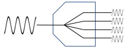
Fig. 1 - Technical sketch of a Wilkinson 1:4 power combiner / power divider
As an example, for signals unrelated in frequency and phase, a two-way combiner with 50 Watts at each input will typically combine to 50 Watts at the common port with 50 Watts lost to internal isolation resistors. Four unrelated 50-Watt signals at the inputs to a four-way combiner will typically combine to 25 Watts at the output with 75 Watts lost to heat.
Still, it is perfectly acceptable to use combiners in this way, so long as the lost power is acceptable. One specificationto be aware of in this regard is the divider/combiner power rating. These devices can always handle more power when used as a divider. This is because, when properly terminated, losses inside the device are much lower than the potential losses when combining. Some manufacturers rate power for the divider application or provide two power ratings: one when used as a divider and a lower rating when used as a combiner.
Wilkinsons and most other power dividers / power combiners typically exhibit isolation between 20 dB and 30 dB. This is not as important when your input signals mirror each other in frequency and phase; it’s very important if the signals do not match at each leg, because you don’t want the signal from one port spilling over to the next.
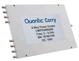
Fig. 2 - Example of an 8:1 Way Power Divider
Nonetheless, these considerations do not detract from the Wilkinson’s ease of implementation as a passive device that can be produced with wide bandwidths. A Wilkinson can handle a bandwidth of up to 10:1 — meaning your maximum and minimum frequencies are separated by a factor of 10x. Some topologies can be narrower, about 2:1.
Finally, Wilkinsons can be low-cost devices, but that cost is affected by a number of factors, including the number of inputs and outputs, as well as the power and the bandwidth. For example, it’s easier and less expensive to implement a 2:1 bandwidth than it is to implement a 10:1 bandwidth.
Multiplexing / Bandpass Filters
If you have multiple signals that must be combined or separated, but they’re all in different frequency bands (e.g., within a cellular network), multiplexers offer a solution. For example, if you need to combine or separate signals at 900 MHz with signals at 1700 MHz, you combine and separate those signals using bandpass filters that are combined at a single point — that’s called a multiplexer.
Specifically, multiplexing allows you to combine and separate different frequency bands with low insertion loss. Unlike a power combiner, multiplexing does not suffer power loss, even when combining incoherent signals — all arrive at the common port at full power (e.g., four 100-W transmitters will combine for 400 W at the common port), minus the internal loss of each multiplexer filter. Filter losses can be low — less than 1 dB — depending upon the size of the filter and the characteristics of the bands to be multiplexed.
Multiplexer isolation is best among the devices we’ll discuss: up to 90 dB or more. If you don’t need that much isolation, you could opt for, say, 40 dB of isolation – reducing the device’s cost, size, and complexity. Further, multiplexer solutions are capable of handling high power levels, and the difference between the highest band and lowest band can span many decades, if you want to go 20-to-1, 100-to-1, or whatever range you need. You could multiplex a 1 GHz signal with a 40 GHz signal.
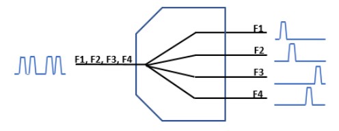
Fig. 3 - Technical sketch of a 1:4 frequency multiplexer
That said, bandwidth and multiplexing have an unusual relationship, in that the overall bandwidth, from your lowest band to your highest band, across all ports, can be great. But the bandwidth within each band usually is comparatively narrow. For example, if you want to multiplex a 900 MHz signal, the bandwidth of that 900 MHz signal typically is no more than about 20 percent (180 MHz).
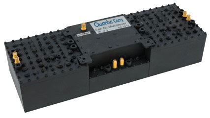
Fig. 4 - Example of a 6 way multiplexer
Additionally, the frequencies can’t overlap — there must be some gap band in between them — and scaling is challenging. The more bands you want to multiplex together, the more difficult things get. Additionally, the closer the bands are to each other, the more difficult things get.
As a general starting point, it’s fair to state that combining one to three bands is fairly standard; combining four to five bands requires some deft thought; beyond that, you will encounter major challenges.
Circulators
Circulators are directional (versus reciprocal) three-port devices; RF signals travel through a circulator from port to port in one direction (i.e., if a signal goes into port one, it comes out port two. If a signal goes in port two, it comes out port three), and the circulator’s isolation characteristics allow only very lossy travel in the opposite direction (Fig.5). This sets circulators apart from the other devices we’ll discuss.
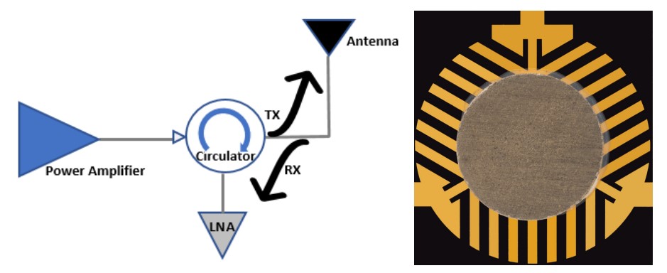
Fig. 5 - (L) Technical sketch of a common circulator; (R) Example of a common circulator
Typically, circulators exhibit bandwidths of 2:1 or less, and they are capable of handling high power with low loss, usually less than 0.5 dB.
Circulators’ isolation hovers around 20 dB (i.e., if you input a signal at port one, it will head to the output at port two, but any signal reflecting back into port two — depending upon the isolation specification — will leak back to port one). It’s worth noting, though, that if you double-gang circulators (Fig. 6), as pictured and described below, you can double the unit’s isolation to 40 dB.
Circulators are advantageous for combining when you have signal directionality. For example, consider an antenna with which you’re trying to both transmit and receive, simultaneously. You can put your transmitter into port one, hook your antenna onto port two, and hook your receiver onto port three. Thus, the signal will come in from your transmitter, go from port one to port two, and out the antenna (emitted as radiation). When functioning properly, received signals from the antenna come into port two of the circulator and circulate to port three, where the receiver is waiting to receive the signal.
Your transmit signal wouldn’t go from port two to port three unless the antenna was disconnected or had poor return loss, resulting in reflection of the signal. In that same vein, if you disconnect the antenna, resulting in an open port, the signal hits the equivalent of a brick wall at port two, reflecting all energies into port three.
The danger here is that reflected transmit power can be delivered to the receiver, along with the desired signals picked up by the antenna. Logically speaking, if the antenna becomes disconnected or fails, you may have a signal amplified to tens or hundreds of watts coming into port one, reflecting off port two, and devastating a sensitive, lownoise receiver rated to handle tiny signals (e.g., in the microwatt range).
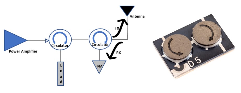
Fig. 6 - (L) Technical sketch of a double-ganged circulator; (R) Example of a dual circulator
A double circulator configuration in this scenario does not solve the problem, but it does prevent the transmit signal from returning to the transmit amplifier. Instead, a load resistor dissipates the signal (Fig. 6). To protect the receiver, a power limiter at the LNA input (not shown) could be used to reflect the signal back to the load resistor and protect the LNA.
90-degree Hybrid Couplers
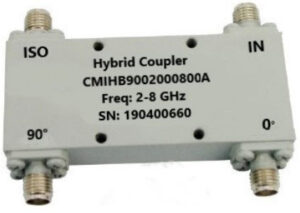
Fig. 7 - Example of a 90-degree hybrid coupler
This device really is a two-way (reciprocal) combiner / divider (much like a Wilkinson, except it’s limited to a twoway split, and the split legs have a 90-degree phase shift). Instead of power dissipation occurring inside the device, though, it’s external at the isolation port; the 90-degree hybrid coupler is a four-port device with one input and two outputs and a fourth isolation port. The device’s fourth port is the reflected port, where you can place an external load to dissipate your heat — a “catch-all” port, of sorts.
These devices draw their name from their role as quadrature couplers, meaning the input is split into two signals that are 90 degrees apart in phase. They exhibit bandwidth that is, at best, 4:1.
Isolation typically is about 20 dB in these devices, but what it does isolate, it throws out to that external power resister, allowing hybrid couplers to handle a lot of power. Thus, power is limited only by the hybrid coupler’s insertion loss (which is low, about 0.5 dB) and how big a load you can put onto it.
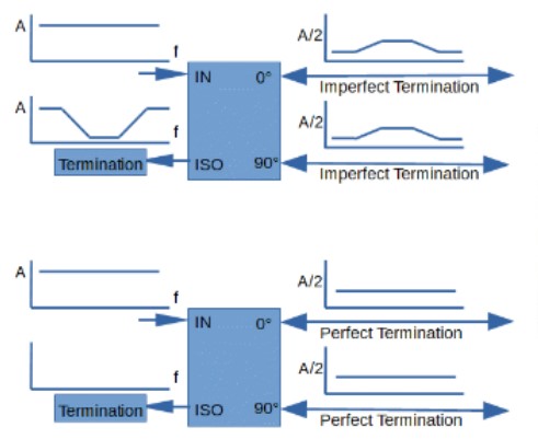
Fig. 8 Technical sketch of two 90-degree hybrid couplers
For example, the top of Fig. 8 shows the transmitted and reflected signals that occur if identical bandpass filters are attached to the two split ports. The in-band signal is split and passed through each filter. Energy outside the passband is reflected back to the isolation resistor. Input return loss is good across the bandwidth of the Hybrid even though the out-of-band signals are not passed on.
The bottom of Fig. 8 shows that little energy, dependent upon the hybrid coupler’s isolation specification, is reflected back to the isolation port if the split ports are properly terminated across the band.
Additionally, 90-degree hybrid couplers are very good at isolating the devices from load mismatches. A good example of this practice’s usefulness can be demonstrated by imagining that Fig. 5’s bandpass filters are actually identical power amplifiers. An RF source can achieve increased amplification by splitting the signal to two amplifiers and then recombining the amplified signals using another hybrid coupler, all while maintaining good return loss.
Conclusions
Determining the optimal RF combining technique for your application ultimately comes down to your signal (or signals) and what you desire to do with it. Can you separate the signals into different frequency bands? What are your application’s power and signal loss requirements?
Quantic Corry has designed and developed each of these components for numerous customers’ applications and has deep experience in helping RF component and systems designers find the appropriate device to fit their needs.
In many cases, using one of the described devices standing alone is insufficient; often, technologies require a combination of these solutions. This is another area where Quantic Corry’ experts can help you to build your complex system – one demanding numerous different receivers, a plethora of antennas, or a combination of switching, power combiners/dividers, and frequency multiplexers.
Take Advantage of Quantic Corry Expertise
Download the Understanding RF Signal Combining Guide

Author Bio
James Price is VP of engineering for Quantic Corry in Warrendale, PA, where his areas of focus include RF and microwave filters, multiplexers, switches and antennas. Price received a BS degree in electrical engineering from West Virginia University in Morgantown, WV, in 1983. From 1985 to 1995, he was an engineer specializing in communications with RCA, which eventually became Lockheed-Martin in Camden, NJ. From 1995 through 2004, he designed CATV products for Tollgrade Communications in Cheswick, PA.